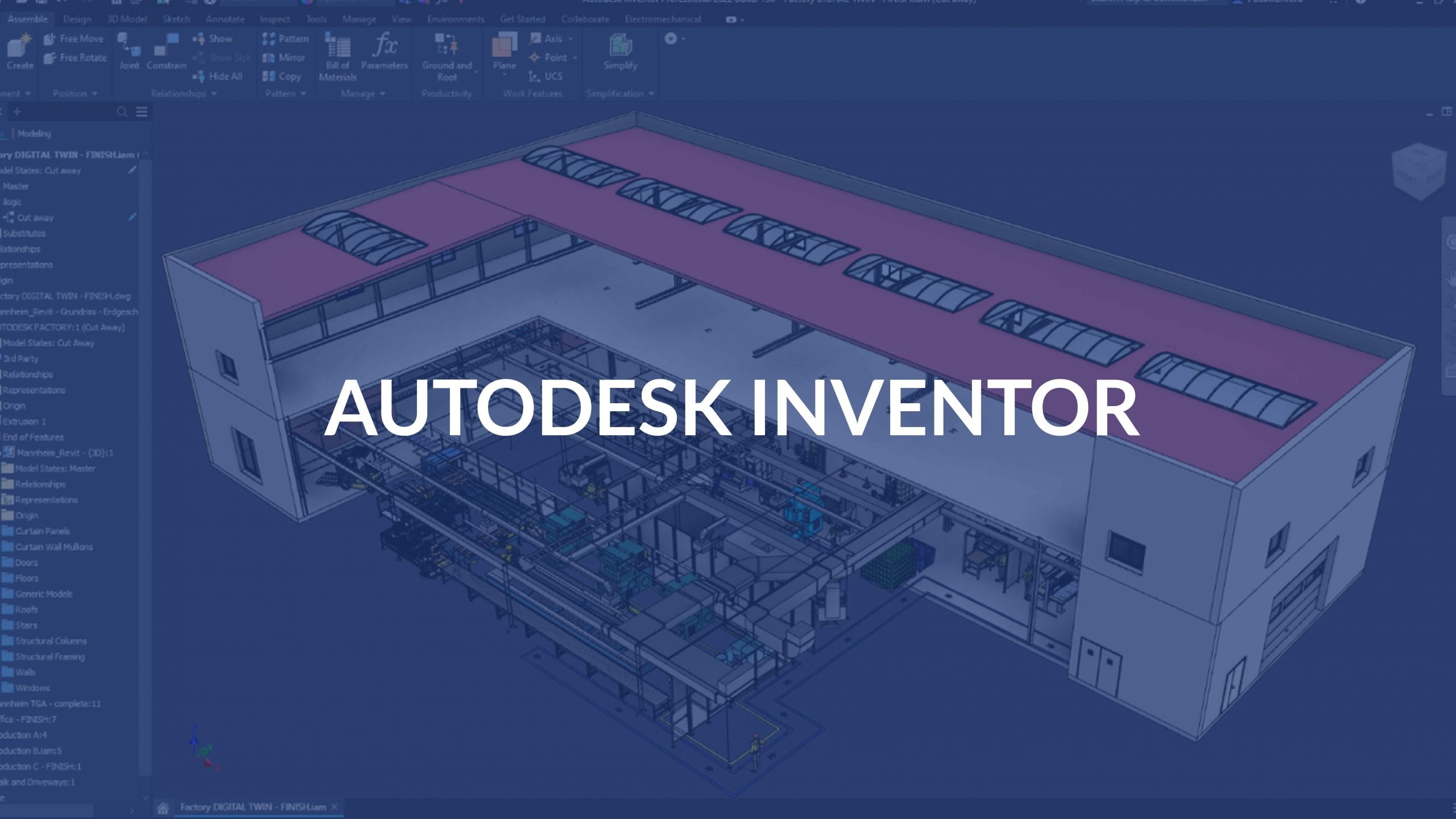
An Autodesk Inventor training outline teaches you to build 3D mechanical designs using “parametric modeling.” Think of this as training a computer with specific rules: if you change one part’s measurement, connected parts update automatically. A standard course progresses through five main steps:
- Getting Started and Sketching
- Learn the user interface (Ribbon, Model Browser, View Cube).
- Draw 2D shapes using lines, circles, and arcs.
- Add “geometric constraints” (rules like making lines parallel or perpendicular).
- Add specific measurements to dimensions.
- Basic Part Modeling
- Turn 2D sketches into 3D objects using tools like Extrude (pulling a shape up) or Revolve (spinning a shape around an axis).
- Add details like holes, threads, fillets (rounded corners), and chamfers (beveled edges).
- Assembly Design
- Combine separate parts together.
- Use “constraints” to mate, flush, or align parts exactly how they fit in real life.
- Create exploded views to see how parts fit inside a product.
- Generate a Bill of Materials (BOM)-a list of all the parts needed to build the product.
- Drawing Creation (Drafting)
- Convert your 3D models into standard 2D engineering sheets (blueprints).
- Create base, projected, and section views.
- Add accurate dimensions and annotations for manufacturing.
Advanced Tools (Optional)
- Sheet Metal Design: Build parts out of flat metal and bend them.
- Stress Analysis: Test if your model will break under physical weight.







Related Articles